Refrigerator Repair & Icemaker Repair
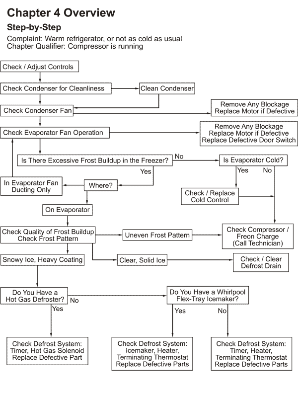
Before you perform any of the other tests in this chapter, make sure that the compressor is running. If it is not running, see Chapter 5.
Some refrigerators are very quiet and smooth when they operate. If you cannot hear your refrigerator running or feel the compressor vibrating, your refrigerator is not working properly and you must investigate further. The chances are your refrigerator is not cooling or not cold.
First, try turning the cold control to the "off" position or unplugging the fridge; this will stop the compressor. Do you hear or feel a difference? If so, the compressor was running. WAIT SEVERAL MINUTES before turning the compressor back on for your diagnostic checks. The reason for waiting before you restart it is explained in section 3-4 (7).
If you perform the above test and do not feel a difference, try "listening with a screwdriver." Access the compressor by opening the back panel and place the metal end of a long screwdriver against the compressor and your ear against the plastic end of the screwdriver. You should hear the compressor running. If you are still unsure and you own an ammeter, test the current draw of the compressor at the compressor leads. If the compressor is running, it should draw about 6 amps.
If your compressor is running and your refrigerator is warm in both compartments (or not as cold as usual, i.e. chilly but meats are thawing,) first check your CONTROLS. You never know if your kids got in there and messed around with them. Set them on mid-range settings. See section 7-1 on KID CAPERS for some interesting stories about this subject.
Inside either the freezer or refrigerator compartment you will generally find at least two dial type controls.
One of them, called the cold control, is an electric switch that starts and stops the compressor based on the temperature that it senses inside the compartment.
The other dial is an air door that controls the small amount of air that passes to the food compartment while the evaporator fan is running. (See Section 1-3)
In some refrigerators, the movement of these air doors is not manually controlled. They may be controlled thermo-mechanically, or even electrically, by a computer board such as the ADC (Adaptive Defrost Control.) But there is usually a knob for setting the temperature that you want in each compartment.
Either dial may be marked with any one of a dozen different labels: "refrigerator control," "freezer control," "food compartment control," etc. Determining which is which can get a bit confusing. If the knob has an "off" setting which stops the compressor from running, it is the cold control.
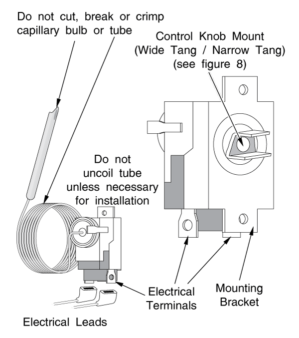
In the absence of an "off" setting, the easiest way to tell them apart is to pull the plastic knob off the control. The cold control will usually have a wide tang and a narrow tang. (See Figure 8) The air door will usually have a plastic or metal "D"-shaped shaft (a round shaft with a flat) to which it attaches, although this is not always the case.
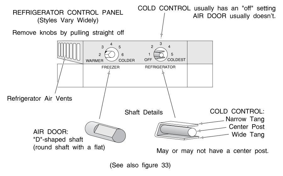
If one dial is in the freezer section and one is in the food section, the one in the freezer section is the cold control, and the one in the food section is the air door.
If the knobs will not come off with a firm pull, or you are still unsure of which control is which, try putting your hand in front of the air vents in the food compartment and manipulating the controls. Make sure the evap fan is running; you may have to tape the door switch so it stays on. If you are manipulating the air door, there should be a detectable difference in the strength of the air draft from the low setting to the high setting.
Often, the first thing that folks do when their refrigerator starts to feel warm is turn both controls on the coldest settings. This is exactly the WRONG thing to do. Turning the cold control to the coldest setting will keep the compressor running longer and make lots of cold air.
But turning the air door to the coldest setting closes the airway to the food section. Lots of cold air is made, but most of it stays in the freezer section, and the food section actually gets warmer.
OTHER CONTROLS:
"VEGETABLE" OR "MEAT" COMPARTMENT CONTROLS BUTTER CONDITIONER, ENERGY SAVER VEGETABLE (CRISPER) or MEAT COMPARTMENT CONTROLS:
These may be small heaters or they may be separate air doors that control the airflow within these compartments. The idea is to keep the compartment at a different temperature from the rest of the food compartment; a more optimum temperature for the particular food that you're keeping in these compartments. Certain high-end fridges are even using thermistor-controlled air doors, and some pretty exotic technologies such as semi-permeable membranes to control humidity in these compartments.
BUTTER CONDITIONERS: Again, small heaters that keep the butter compartment at a different temperature than the rest of the food compartment.
"ENERGY SAVER" OR EFFICIENCY SWITCHES:
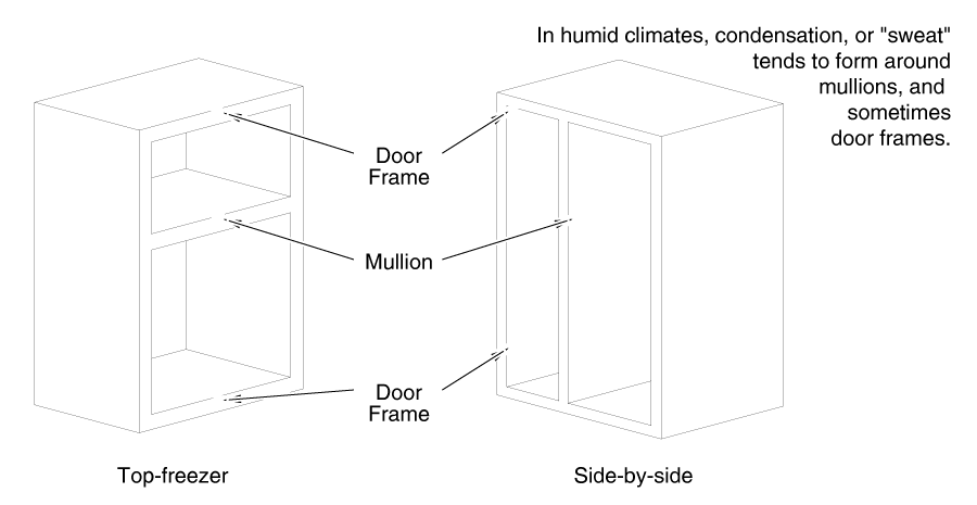
If you live in a warm, humid environment, you may have a problem with condensation forming on the outside of your refrigerator. This is known as "sweating." So-called "Energy Saver" switches control small, low-wattage "mullion" heaters in the side and door panels that prevent the outside of the refrigerator from getting cool enough for sweating to occur. In the "economy" position, the heaters are off.
If the refrigerator has cooling problems, often the first symptom will be that the mullions start to feel warm.
Next, check your condenser and condenser fan.
The locations of the most common types of condensers are shown in Figures 9A, 9B & 10. Any type condenser mount may be used on bottom-freezer, top-freezer or side-by-side units.
FIGURE 9A: A back-mounted condenser has no condenser fan. Air flows over it by convection; the warm air rises and is replaced by cooler air from below. Some of these condensers are covered by a metal plate.
FIGURE 9B: Bottom-mounted condensers come in many configurations. Most look like a radiator or grille beneath the fridge, behind the kickplate. They are accessible for cleaning through the bottom front of the refrigerator. A condenser fan moves air across these condensers.
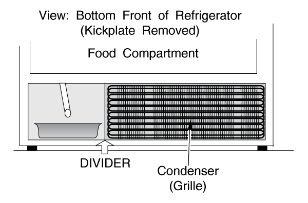
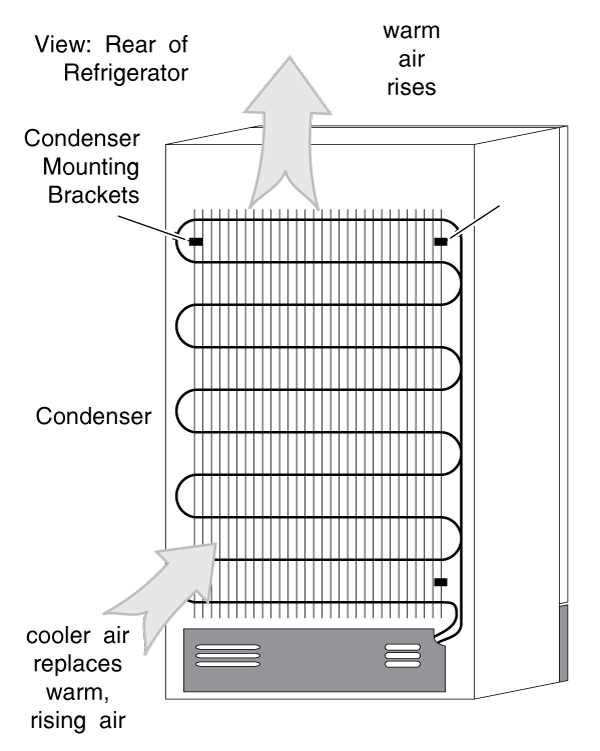
FIGURE 10: Another fairly common type of bottom-mount condenser is wrapped in a metal plate and is accessible through the bottom back panel of the refrigerator.
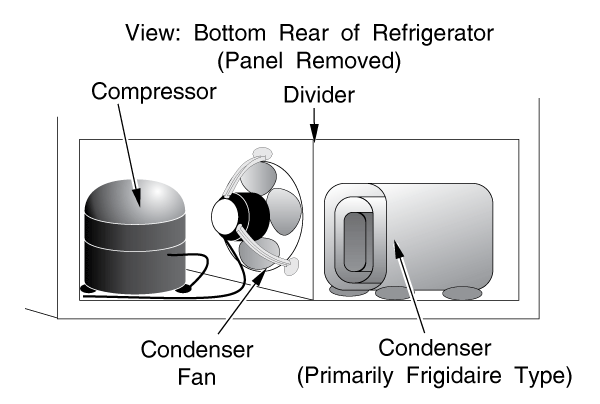
The condenser fan may be mounted in a number of different ways. Usually it is accessed by removing the bottom back panel. Figures 10 & 11 show the most common arrangement for the condenser fan.
DIAGNOSIS AND REPAIR
If you have a back-condenser refrigerator, make sure that nothing has fallen behind your fridge that might block the airflow.
If you have a bottom condenser, remove the baseplate (kickplate) from the bottom front of the refrigerator and look beneath it with a powerful flashlight. If you have kids or dogs or if your clothes dryer is installed nearby, you are a prime candidate to have a blocked condenser.
Quite a bit of dust is normal; still, enough may be impacted to block the airflow completely. Feel for a steady flow of warm air from the drain pan side; it should be obvious (see Figure 11). Clean your condenser with a condenser brush. (NOTE: Some condensers must be accessed through the back panel.)
CAUTION: When cleaning your condenser, you want to do it thoroughly, but don't be too vigorous about it. You don't want to knock loose any wiring beneath the fridge. Also, you may hit the condenser fan (with a grinding thud) with the brush. Don't worry too much about it; you probably won't hurt the fan or motor, though it is something you want to avoid if possible.
If the airflow improves dramatically, then that may have been your only problem.
After you clean your condenser, pull the lower back panel off the fridge. Make sure that the condenser fan is running and not blocked by any loose insulation or other objects.
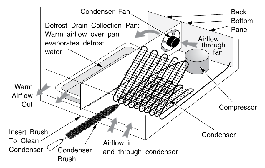
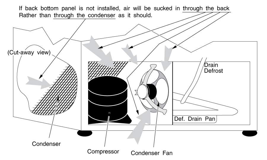
MAKE SURE THAT YOU REPLACE THE BACK BOTTOM PANEL!!! If it is missing, fashion one out of a piece out of corrugated cardboard and screw it on using the existing screwholes. It has the very important job of directing airflow beneath the fridge, assuring that the condenser fan is drawing air over the condenser and not just sucking air in through the back of the fridge. (Figure 12)
If the condenser fan is stopped and there is nothing blocking it, replace the fan motor. They are sealed units and cannot be rebuilt.
Replacing the condenser fan motor can be dirty and difficult. There are two types of mounts most commonly used; (Figure 13) bracket mount (the most common) and pedestal mount.
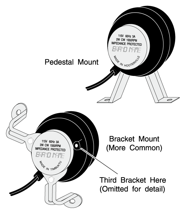
It is usually easiest to remove the mounting brackets or pedestal from their place in the refrigerator, with the fan motor attached. When installing a new motor with bracket mounts, it may be easier to install the brackets loosely on the motor until you can locate the mounting screws in their holes. The wires can be cut and re-connected with crimp-on butt connectors or wire nuts and electrical tape.
Even if you find a dirty condenser or stopped condenser fan, it's a good idea to go through the rest of the tests in this chapter to be certain that you've solved your problem.
On some models, the evaporator fan shuts off via a door switch when you open the refrigerator door. Thus, when trouble-shooting the evaporator fan, you must depress the door switch(es).
Open your freezer door, depress all door switches and listen for the evaporator fan. If you do not hear it running, there's a problem. It might be ice-blocked, or it might have worn out and stopped. The door switch that operates it might be defective. If you do hear the evaporator fan running but you do not feel a strong blast of freezing air from the freezer vents, then you probably have a frost problem; see section 4-4.
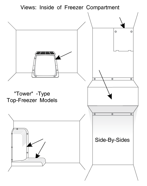
IF THE EVAPORATOR FAN IS NOT RUNNING, You may need to pull off the entire evaporator panel as described in section 4-4 to access the fan. Look first for a separate access panel or a tower within the freezer that houses the fan (Figure 14). Check for anything that may be blocking the fan, including ice from a backed-up defrost drain or a frost problem. If something is blocking the fan, clear it out of the way. If the blockage is due to frost or ice, you must investigate the source and solve the problem.
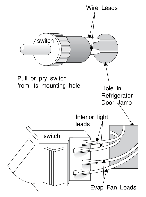
Depress the door switch. If nothing is blocking the fan and it still does not run, check for voltage across the fan motor leads (with the door switch depressed, of course.)
If you have voltage across the fan motor leads, the fan motor is bad. Replace it. If you don't have voltage to the fan motor, the door switch might be bad. Take power off the fridge and pry out the door switch. You might have to destroy it to get it out. Check for voltage to the switch. If the switch is bad, replace it. (Figure 15).
SLOW-RUNNING EVAPORATOR FAN MOTOR
Sometimes the evap fan will run slower than it should. This can be difficult to diagnose. It can cause ice to build up in the internal ductwork.
If you hear a "whistling" or "warbling" noise emanating from the fan motor itself or from the inside of the food or freezer compartment, it is probably coming from the evaporator fan motor. The bearings are worn and loose or sticky. Replace the motor.
As I said, a slow evap fan can be very difficult to diagnose. Usually it is done by sound and by experience. The chances are, if it sounds slow or strange, it is malfunctioning. Try replacing it. They don't cost much.
REPLACING THE EVAPORATOR FAN MOTOR
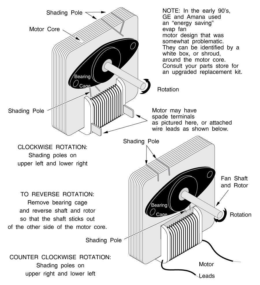
In replacing the fan motor, you must make sure that the rotation of the new fan motor is the same as the old one. The easiest way to do this is to look for the shading poles on the old fan motor (Figure 16).
If they are on opposite corners from the ones on the new fan motor core, it is a simple enough task to reverse the new rotor in its core. Carefully remove the bearing cage screws and simply turn the rotor around so the shaft sticks out the other end of the motor.
Remove everything from your freezer, including all food and any shelves. Do not remove the icemaker (if installed.)
Look at and feel the panel covering the bottom or back of the freezer compartment. Is it thick with frost?
On top freezer models, are the holes in the top of the food compartment that lead to the evaporator choked with ice?
Is there ice forming on, or lots of water on the ceiling of the food compartment?
If the answer is yes to any of these questions, there's probably a defrost problem.
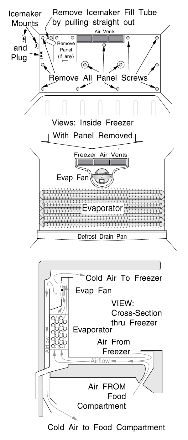
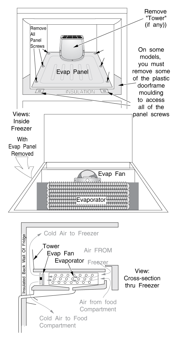
If you suspect a defrost problem, first remove any icemaker that may be installed. You will see a removable panel covering the entire back or bottom of your freezer compartment. There may be 6 to 10 or more screws holding it on. (Figures 17, 18 & 19) In some units there is a light socket attached to the panel; you'll see this arrangement most often in side-by-sides.
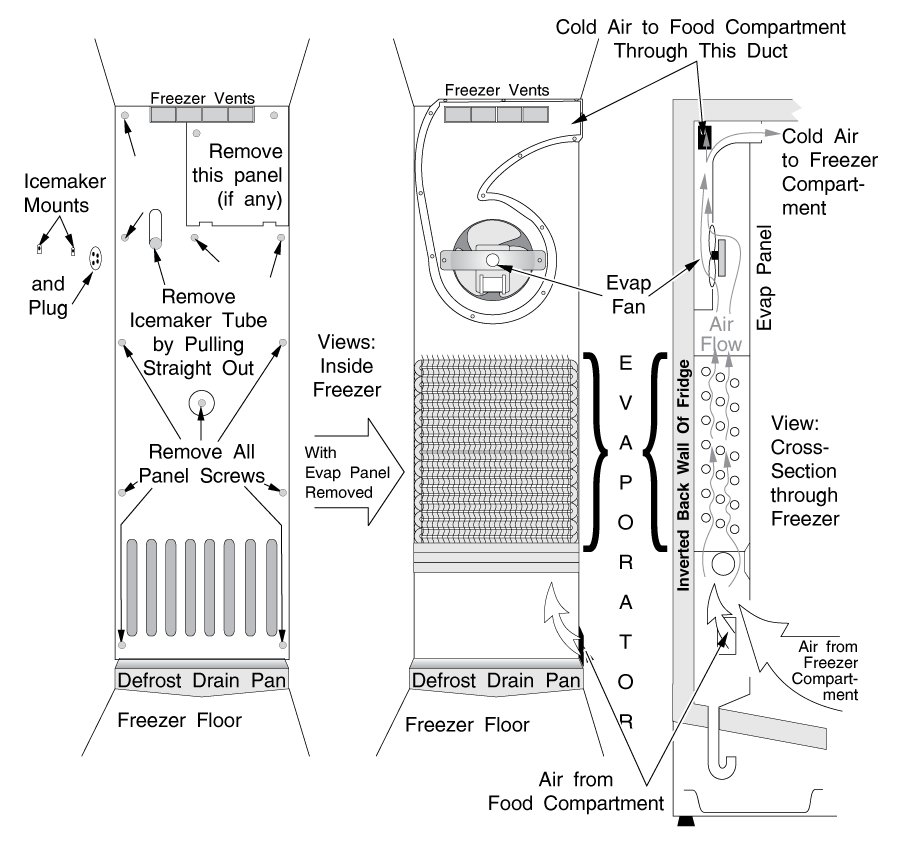
These can sometimes be quite difficult to disassemble. Make sure the power is off the refrigerator before disassembling any lighting circuit.
On some bottom-evap models, you may have to remove some of the plastic moulding around the door frame to access some of the evaporator panel screws. (Figure 19) Be extra careful; the plastic moulding can be brittle and break easily. The plastic will bend; just go slow. You may even try heating it a little with a blow dryer, to soften it.
The panel may be frozen to the evaporator; be careful you do not bend or break it. Sometimes it pays to take a few extra minutes and melt the ice a little bit first. This can usually be accomplished by placing a pan of very hot water in various places on the panel, or by blowing warm air on it with a blow-dryer. Do not melt all the ice just yet; only enough to get the panel off. You want most of it to remain there at this point so you can further diagnose the problem.
NOTE: The terminating thermostat opens at a temperature of somewhere between 40 and 90 degrees F, depending on the design of your fridge. Most are between 50 and 70. It does not close again until well below 32. Ice is cold enough to keep it closed, but not to close it again if it opens. Therefore, when you are diagnosing a defrost problem, it's a good idea to try to avoid melting the ice encasing the terminating thermostat until you've made your diagnosis. If the thermostat opens before you've had a chance to see if the heater works, you'll have to by-pass it. On some models, this involves cutting, stripping and splicing wires. No big deal, but it's an extra step that's unnecessary if you're careful about melting ice in the first place.
Some of the styrofoam insulation panels may be waterlogged and may break when you remove them. It's okay, just keep them in one piece as much as possible and replace them as best you can when you're re-assembling.
EVAPORATOR TYPES
There are countless different arrangements for the evaporator and its fan and ducting, but almost all arrangements are relatively simple and easy to trace.
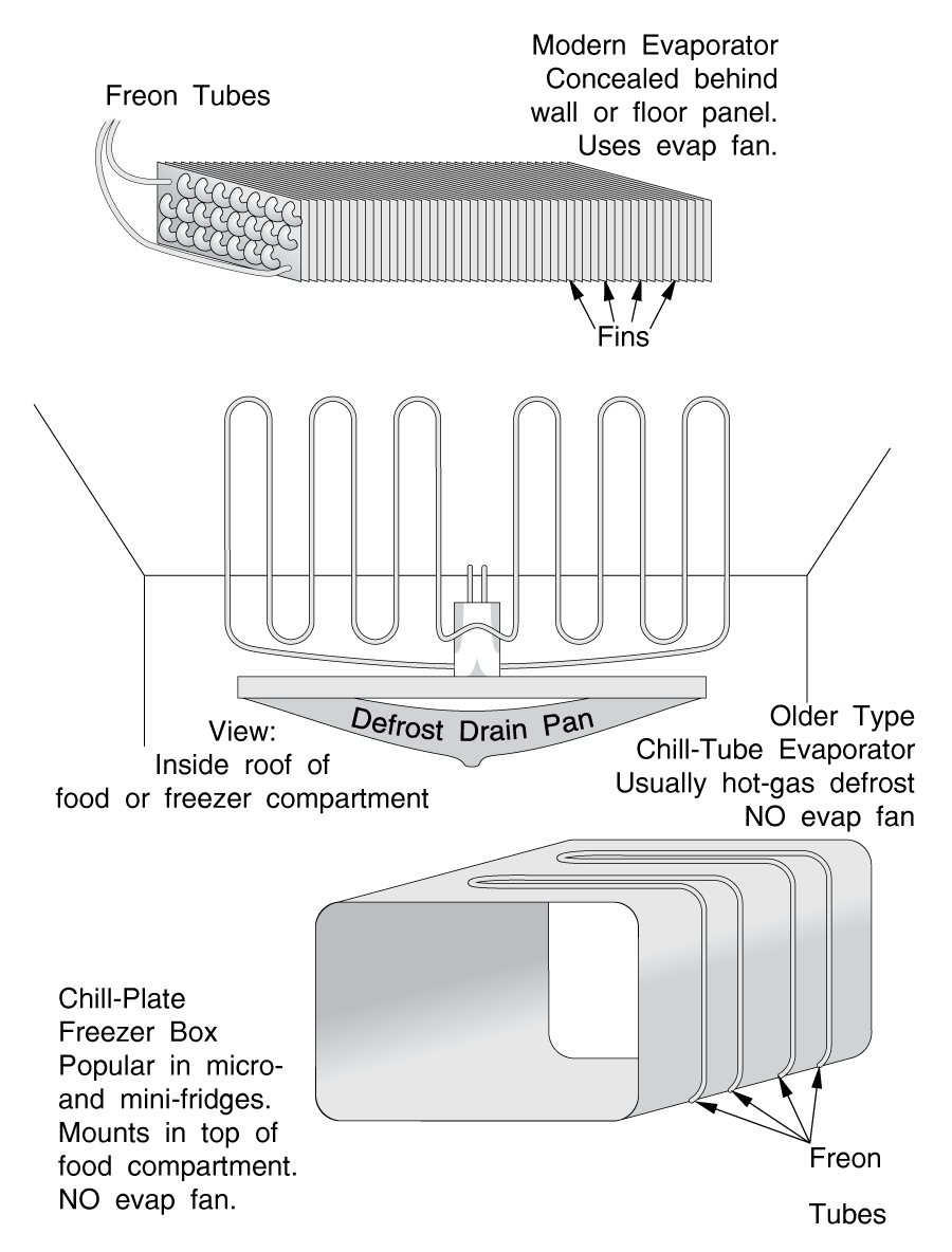
The evaporator looks like a group of looped aluminum tubes, usually with fins attached. The fins are sharp; be careful not to cut your hands on them.
Chill-plate evaporators look like a silver aluminum plate, sometimes in the form of a box. There are many styles, but most are variations of the three types pictured in Figure 20.
A back-evaporator model is one with the evaporator mounted vertically against the inside back wall of the freezer compartment. These may be bottom freezer models, side-by-sides (Figure 17) or top freezer models (Figure 18.)
A bottom-evaporator model is one with the evaporator mounted horizontally (flat) beneath a panel on the bottom of the freezer compartment (Figure 19). These are generally top-freezer models only.
WHEN YOU GET THE PANEL OFF, examine the quality of the ice that's built up on the evaporator. Is it frosted heavily enough to block the airflow, or is it just a thin white coating? Does it have a fluffy (snowy) white consistency, or is it solid and clear-ish or slightly milky white-ish?
Check the frost pattern. Is the evaporator frosted on one or two coils, and then clear on the rest? Or is it pretty evenly frosted? Or is it not frosted at all?
On back-evap models, examine the drain pan directly beneath the evaporator. Is it clear, or is it filled with solid ice?
Each of these symptoms indicates a different problem. If you have solid ice, see Chapter 6. If no coils are frosted, or just one or two, see "UNEVEN FROST PATTERNS," section 4-8. If you see a thin, even, white coating of ice on the evaporator, and no ice in the defrost drain pan, the defrost system is probably O.K.; go to section 4-9. If you have lots of white, snowy ice, keep reading.
If the frost is snowy and white in appearance, you have a defrost problem. The three main components of the defrost system are the defrost timer, the defrost heater and the terminating thermostat.
In most older refrigerators and some newer ones, a motor-driven timer (Figure 21) is used to stop the compressor and initiate a defrost cycle. This timer controls how often the cycle occurs, and how long the defrost heater stays on. This is a fixed cycle; for example, the refrigerator might stay in the cooling cycle for 10 hours, then spend 20 minutes in the defrost cycle.
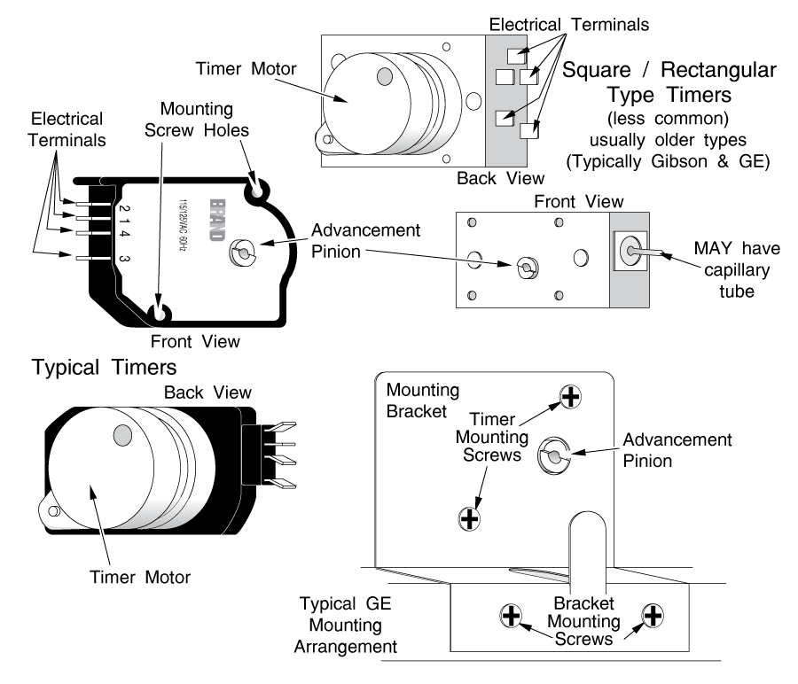
There is one type of older refrigerator that uses a different kind of motorized timer. If you have a Whirlpool or Kenmore refrigerator with a flex-tray icemaker, the defrost timer is integrated into the icemaker. It is NOT a separate unit, like those shown in Figure 21. This is true whether you are using the icemaker to make ice or not; it is running constantly to time your defrost cycles. If you have a defrost problem and you have one of these machines, follow the instructions in section 4-6.
Nowadays, refrigerators are being made as efficient as possible, due in no small part to government energy efficiency requirements. Defrost heaters use a lot of energy, so designers are mimimizing the total amount of time that the heater is energized. The trick is in achieving a balance; that is, keeping the evaporator as clear of frost as necessary for efficient heat transfer, while energizing the heater as little as possible.
In practical terms, this translates to trying to reduce the duration of the defrost cycle (the length of time that the heater stays on) and to lengthen the defrost interval (the length of time between defrost cycles.)
Obviously, refrigerators operate under a wide variety of conditions, all of which affect the amount and speed of frost buildup. Such factors include ambient humidity and temperature, the water content and temperature of the food you put into the fridge, icemaking within the freezer, and how often the door is opened and closed.
For example, if you go away on vacation for a week, the refrigerator door will obviously not be opened for a long time. Less humid air will enter the fridge than if someone was at home, and opening and closing the door. Frost buildup will be much slower than usual, so the refrigerator will not need to be defrosted as often as normal. It also will not need to be chilled as often, so compressor run times will be shorter and less frequent.
Designers are using microprocessors (on solid state circuit boards) to adapt defrost intervals and durations to compensate for differences and changes in operating conditions. Such techniques are called Adaptive Defrost Control, commonly abbreviated as ADC.
To make decisions about the correct defrost duration and interval, the control board must have input about the conditions that the fridge is operating under. Each manufacturer uses a different logic scheme and different inputs, such as door open time, compressor run time, duration of the previous defrost cycle, and duration and intervals of door openings.
Door open info is provided to the logic board by the door switch - the same one that controls the refrigerator's internal lights. If the light bulb is not working, the ADC will still accumulate door open time. However, if the door switch has failed, the next defrost will occur either too quickly or too slowly.
Some designs even have a vacation mode; for example, the refrigerator will not defrost as often if the door has not been opened in 72 hours.
Some ADC / control boards control other functions of the refrigerator, too, such as icemaking and electrical air damper door opening and closing.
The defrost frequency may also be shortened under certain circumstances. For example, the ADC is programmed with a maximum amount of time that the heater can stay on; say, for 16 minutes. If the heater stays on for the maximum amount of time, without being terminated by the thermostat, the microprocessor will assume that not all of the frost melted, and it will initiate the next defrost cycle much sooner.
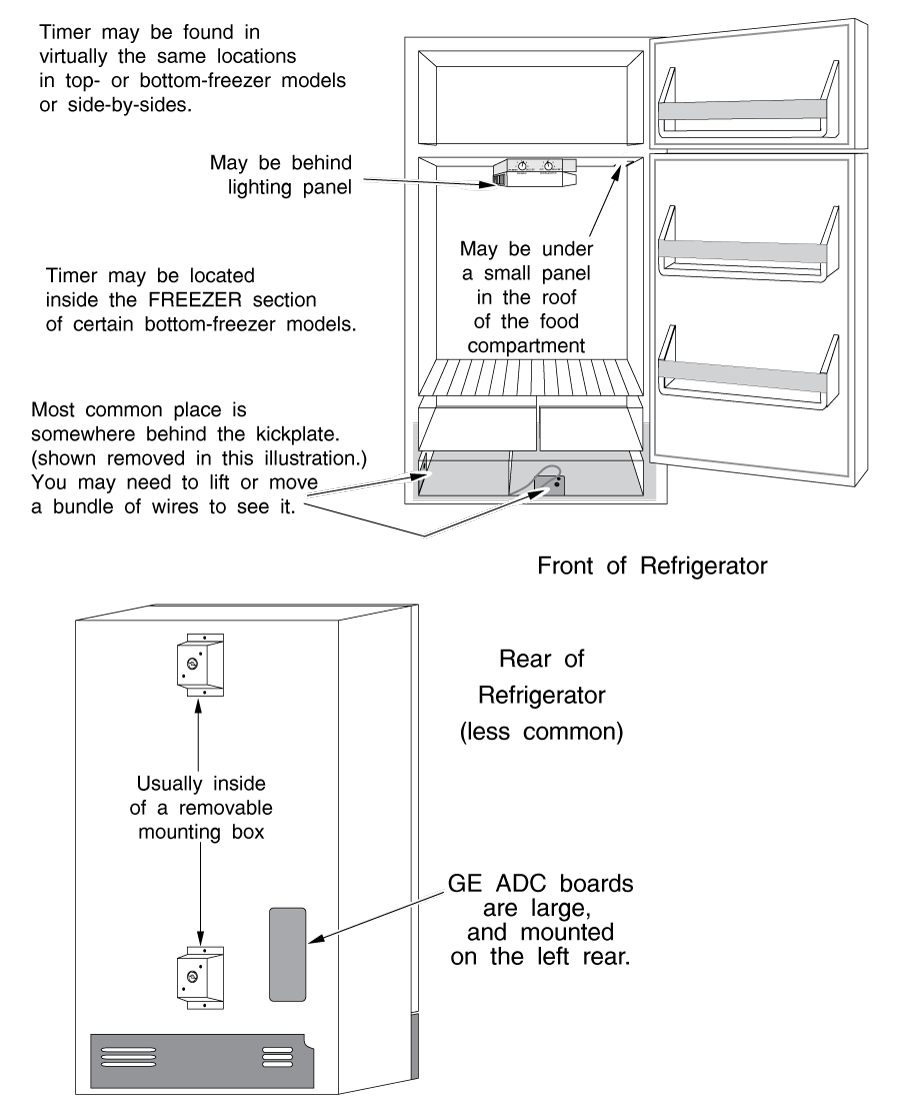
DEFROST TIMER AND
ADC BOARD LOCATIONS
Mechanical defrost timers can be a bit difficult to find. They come in many different styles. Often they are mounted under a cover plate or in a bracket that hides all but the advancement pinion. Figure 21 shows some different style timers and what the timer might look like installed; Figure 21A shows some typical mounting locations.
ADC boards are mounted in similar locations to defrost timers. However, they do not look the same as a mechanical timer.
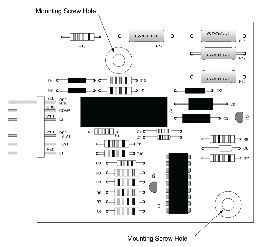
Being a solid-state circuit board, they do not have an advancement pinion; defrost is initiated differently than with timers (See section 4-5(d).) Figure 21B shows a typical ADC board. The easiest way to recognize them is that the harness connection is always labelled with the compressor, defrost heater, L1 and L2. Often the leads are labelled for the defrost thermostat, too, and a sometimes even test connections.
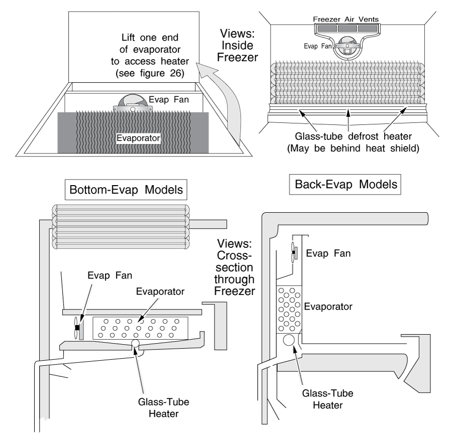
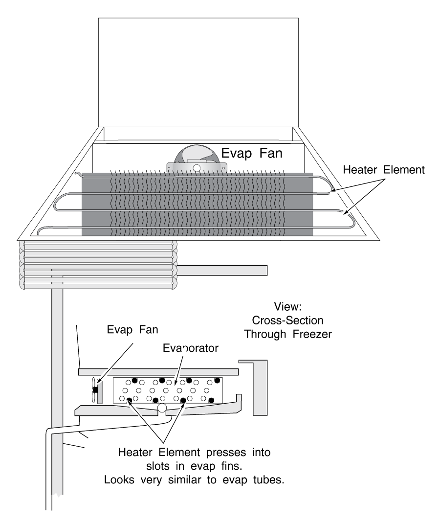
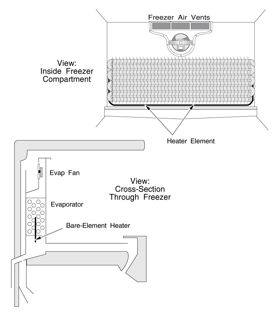
Defrost heaters are always located in the evaporator compartment. See Figures 22A, 22B, 22C & 22D for arrangement and types. There are three different types most commonly used:
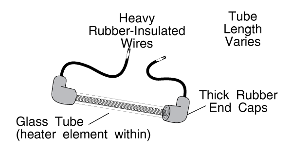
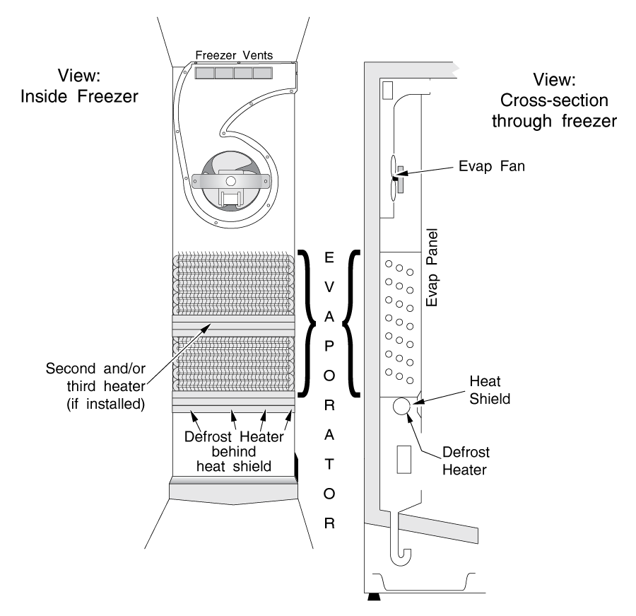
22, 22A, 22B) Glass-tube defrost heaters: The heating element is encased in a glass tube mounted beneath the evaporator. Sometimes two or three small glass-tube-type heaters will be used instead of one big one; usually you'll see this arrangement in side-by-sides.
22C) Aluminum tube heaters: These heaters look just like the evaporator tubes and press into the evaporator fins. They are usually used on bottom-evap models. The easiest way to see the heater is to look for the heavy, rubber-coated wires leading to it; one on each end. Often there are clips holding the ends on to the evaporator coils; watch for these when you remove the heater.
22D) Bare element heaters: Found most commonly on top-freezer back-evap models. The element has no protective tubing and generally wraps around beneath the evaporator in a large "U" shape.
You must exercise caution when handling these heaters to prevent burning yourself. They all run very hot; glass tube and bare element heaters even glow red while in operation.
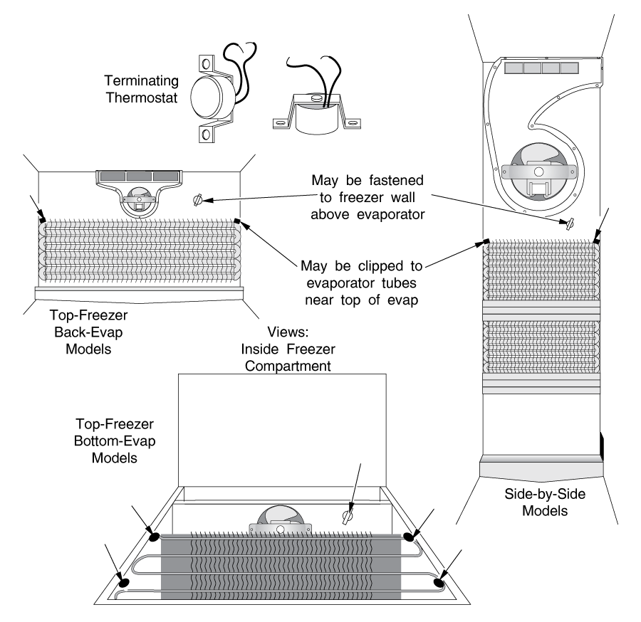
A terminating thermostat will also be located somewhere in the evaporator compartment, usually to the evaporator itself (by a spring clip) or against the side or back wall of the compartment.
It looks like a small cylindrical disc about 1″ or so in diameter and about 3/4″ to 1″ thick (Figure 23.)
It is wired in series with the defrost heater; when it opens, the heater shuts off. One of the two heater wires will lead directly to it.
Defrost starts when a timer turns on the defrost heater. The timer may be mechanical and motor driven, or it may be an electronic ADC board.
Defrost stops when one of two things happens.
If the evaporator is lightly frosted, the frost will melt fairly quickly. If that happens, you want to turn the heater off soon after the ice melts, to prevent the evaporator compartment from heating up too much. If the terminating thermostat senses too high a temperature in the compartment, it opens, and cuts power to the heater. The thermostat will then stay open until the compartment again reaches a very low temperature. In other words, it waits to reset itself until the cooling cycle starts again.
If the evaporator is more heavily frosted, the ice may not all melt within the time allotted by the timer. In this case, the terminating thermostat will remain closed throughout the defrost cycle. The heater will stay on until the timer stops the defrost cycle, and restarts the cooling cycle.
If you initiate defrost (turn the timer on) and the heater does not heat up, then usually the heater or terminating thermostat is bad. If you initiate defrost and the heater does turn on, then usually the timer or ADC board is bad, and you must replace it.
To diagnose which component is bad, you must initiate the defrost mode, or test continuity through the defrost heater and terminating thermostat. How you initiate defrost depends on whether you have a mechanical defrost timer or an ADC board.
INITIATING DEFROST: MECHANICAL TIMER
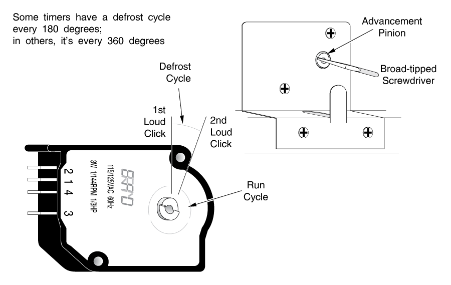
If you have a mechanical defrost timer, find the timer (see section 4-5(a).) Put a screwdriver in the advancement pinion and advance it (clockwise only, or you will break it). (Figure 24) Sometimes it takes a pretty firm twist to advance it. You will feel it clicking. At some spot in the cycle, you will hear and feel a loud click; after you advance it 10-20 more degrees or so, you will feel and hear another loud click.
Between the two loud clicks is the defrost part of the cycle. The rest of the timer's rotation is the "run" cycle. If your compressor is running when you advance the defrost timer, it will stop running when you hit the defrost portion of the cycle.
Advance the timer all the way around to the beginning of the defrost cycle again (generally one-half or one full turn) and leave it as early in the defrost cycle as possible.
Now skip ahead to DEFROST HEATER DIAGNOSIS. If you have a hot-gas defroster, go now to section 4-7.
INITIATING DEFROST - ADC
If your fridge has Adaptive Defrost Controls, how you initiate defrost depends on the brand. See Appendix A in the back of this manual for instructions.
DEFROST HEATER DIAGNOSIS
Look and listen to the evaporator. Within ten minutes (usually much less) you should be able to see a red glow from the defrost heater(s), which is (are) mounted beneath the evaporator.
If you have an aluminum-tube heater as described in section 4-5(b), it will not glow red, but you will see ice melting away from its coils. Be careful; all defrost heaters run hot enough to burn you. You will probably also hear popping and sizzling; this is defrost water hitting the heater and boiling off.
If you do see or hear any of these indications, the problem is the defrost timer or ADC board; it is not initiating defrost. Timers can get old, worn and coked up with dust, and may develop hard spots in the bearings. If you do not hear or see indications that the defrost heater is working, then it is necessary to investigate a little further. Go to Section 4-5(e).
REPLACING THE DEFROST TIMER
If the problem is your timer, it must be replaced.
If the timer is connected by a terminal block, it probably plugs in directly.
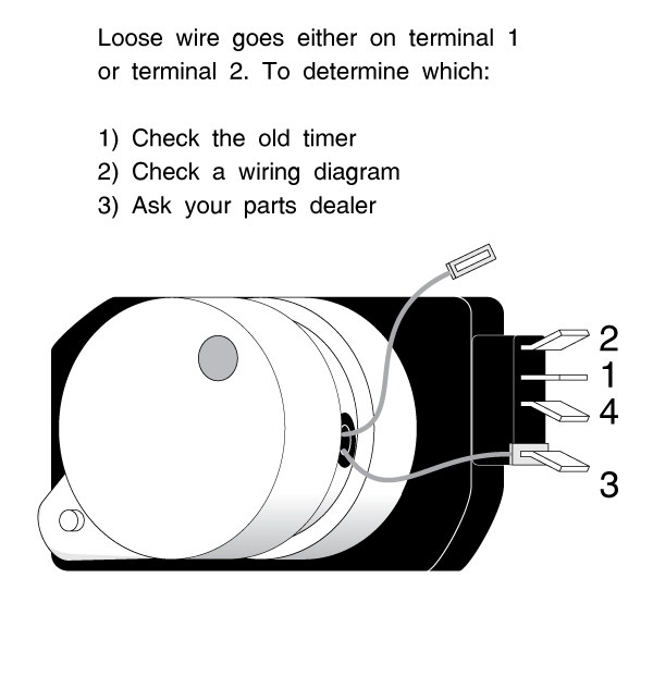
If you have separate wires to the timer terminals, carefully record which wire came off which terminal, by color or by terminal number, or both. Draw a picture, if you have to. Make sure that the new timer is wired correctly; there should be instructions with the new timer.
CAUTION: If you have a Whirlpool or Kenmore timer with a separate wire coming from the timer motor, (Figure 25) it is important to get that wire connected to the proper terminal. If the wire is visible on the old timer, connect it to the same terminal. If you cannot tell for sure, get the information for your model fridge from your parts man. If the timer is wired incorrectly, the fridge will frost up again.
Thoroughly melt all the ice in the evaporator compartment and in the air ducts leading to and from the compartment, and re-assemble your fridge.
If you do not hear or see indications that the defrost heater is working, you could be looking at one of several different problems. The heater element may be burnt. The heater may be so icebound that it would take hours for the heater to melt enough ice for you to see the heater begin to work. The terminating thermostat might be open.
Whether you have an ammeter or not, if you think the defrost heater is not working, test it for continuity.
If you don't have an ammeter, thoroughly melt all the ice in the evaporator compartment and find the proper power leads for your heater. If they are not connected to a terminal block, you will need to cut the leads to test for continuity. Make sure you're not testing continuity across the terminating thermostat too; it may be wide open above 40 or 50 degrees. If the heater shows good continuity, it is working fine. If you have more than one heater, test each, unless they are permanently wired in series. If they are permanently wired in series, test them as a set. If the heater is bad, replace it. If you have multiple heaters, replace them as a set. With glass-tube heaters, be careful that the glass is not cracked or broken and that you do not cut yourself. It is a good idea to replace the terminating thermostat with the heater(s). It's cheap.
If you have an ammeter, try to determine if the heater is drawing any power before you melt any ice. If so, it will be drawing between about 2 and 5 amps. In trying to find the heater leads, be careful that you do not melt so much ice that the terminating thermostat opens. If you suspect that the terminating thermostat might be open, temporarily bypass the terminating thermostat with an alligator jumper as described below.
If you cannot find the heater leads, an alternativeis to check the current in one lead of the main power cord. (See Figure 7 in Chapter 3)
If the fridge is in the defrost cycle and the interior lights are off, then the only current draw will be the defrost heater.
If the heater(s) test out O.K., then the problem is your terminating thermostat. Double-check this diagnosis by jumping across (shorting) the terminating thermostat with your alligator jumpers. If the two thermostat leads are not on a terminal block, you will have to cut the leads to jump the thermostat. Start the defrost system as described earlier in this section. If the defrost heater now heats up, your terminating thermostat is definitely bad. Replace it.
In replacing heaters and/or terminating thermostats, you can use butt connectors, wirenuts, and electrical tape, or spade connectors if fitted. Remember that it's a wet environment.
LIFTING THE EVAPORATOR
If you have a bottom-evap model fridge, replacing the heater will involve the delicate task of lifting the evaporator up to get to the heater. (See Figure 26)
The Freon tubes leading to the evaporator will both enter the evaporator at one end. If you break or puncture one of those tubes, you're looking at a potentially expensive sealed system repair.
Thaw out the evaporator as thoroughly as is humanly possible. The closer the tubes are to room temperature, the more malleable the metal will be. Do not heat the tubes. If you are changing an aluminum-tube defrost heater, remove any clips holding it to the evaporator and loosen the top heater coils from the evaporator fins.
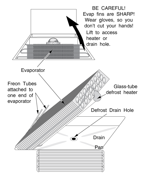
The evaporator fins are sharp; be careful you don't cut yourself. Remove the evaporator mounting screws (if there are any) and gently lift up the end of the evaporator opposite the tubes. Prop up the evaporator with a blunt instrument (I use my electrical pliers or a flashlight) and change the heater. While you're in there, make sure the drain is clear as described in Chapter 6. Do what you went in there to do, but as much as possible, avoid moving the evaporator around too much.
When you finish, gently lower the evaporator back into place. Always reinstall any little chunks of styrofoam or duck seal that you may have removed from beside the evaporator; they keep the air flowing through the evaporator rather than around it.
Re-assemble the fridge.
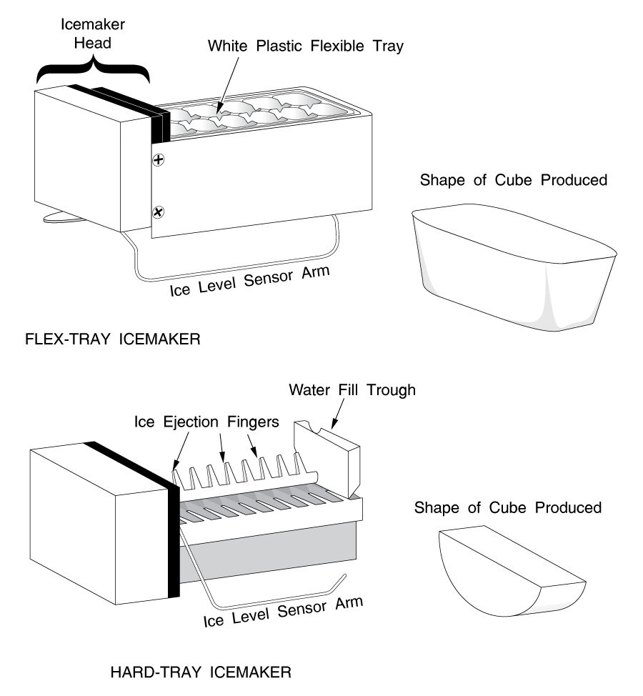
You can recognize this type of defrost system by the shape of the cube it puts out (or would put out, if it was working). The hard-tray Whirlpool/ Kenmore produces "half-moon" shaped cubes (see Figure 27.) The flex-tray produces "rounded rectangular" cubes. The hard tray is finished in a dark gray or black color and has rotating fingers that eject the cubes from the unit; the flex-tray has a white plastic, flexible tray that inverts and twists to eject, much the same as a manual ice cube tray would work. The hard-tray and separate defrost timer is by far the more common arrangement.
This defrost system has the same components described in the defrost system in section 4-5, except that the defrost timer is integrated into the icemaker. Whether it is being used to make ice or not, the icemaker motor runs whenever the compressor is running.
The defrost components will act the same, and you test them in the same manner as described in section 4-5, except for one item:
You cannot advance the icemaker like you can advance a defrost timer. However, the actual switch that controls the heater is accessible.
HOW TO REPLACE THE GEARSET
Remove the icemaker and the evaporator panel as described in section 4-4. YOUR COMPRESSOR WILL STOP RUNNING WHEN YOU UNPLUG YOUR ICEMAKER. DO NOT BE ALARMED. Remove the ice tray from the icemaker. It is spring loaded and simply pushes away from the icemaker head and pops out. Take the plastic cover off the face of the icemaker and remove the three screws holding the metal faceplate to the icemaker head. (See Figure 28) Remove the drive cam, the large drive gear and the smaller timing gear. You will need to remove the leaf switch to get the drive cam off. Examine the gears for any stripped teeth. If you see any, replace the gears and drive pin as a set.
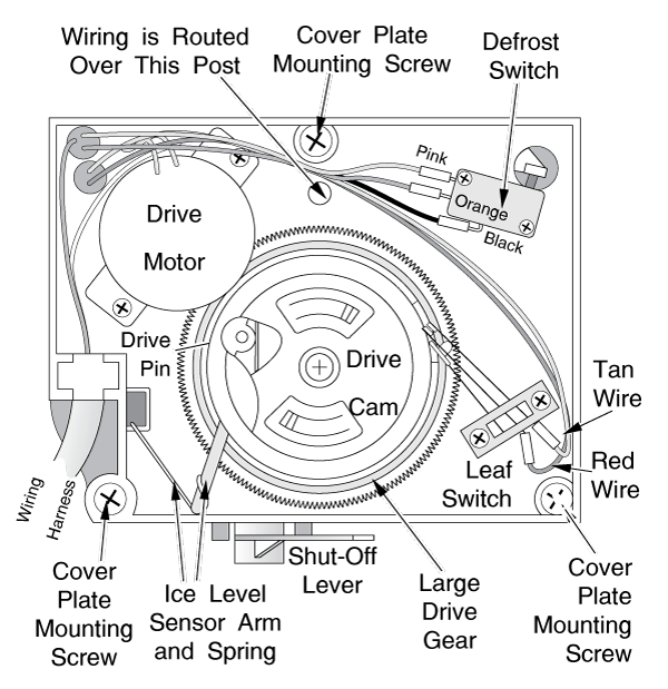
Temporarily remount the leaf switch to keep it from drifting around and touching things.
Inside your fridge, turn the cold control to its coldest setting. Plug the icemaker back into its electrical socket and observe the drive motor in the upper lefthand corner of the icemaker head. When the compressor is running, the motor will turn very slowly. If it doesn't, it is bad. Replace it.
Unplug your icemaker and look into the icemaker head. The defrost switch is the small, rectangular switch in the upper righthand corner of the icemaker head. Remove this switch from its mounts, but do not disconnect the wires to it. Using electrical tape, tape it out of the way so it does not touch any other metal object in the icemaker head. Plug in the icemaker again. Do not touch any metal contact with your hands; you may shock yourself.
Within a few minutes, you should start to see signs that the defrost heater is working as described in section 4-5(d).
IF YOU SEE OR HEAR NO SIGNS OF THE DEFROST HEATER HEATING UP, unplug your icemaker, remove the BLACK lead from the defrost switch and electrically test the switch for opening and closing. Using your resistance meter, you should see continuity (and no resistance) between the empty terminal (where the BLACK lead was) and the PINK terminal.
You should see NO continuity between the empty (BLACK) and ORANGE terminal. When the switch toggle is depressed, continuity will be just the opposite: BLACK-ORANGE-CONTINUITY, BLACK-PINK-NO CONTINUITY. If the switch is not acting right, replace it. If the switch is okay, the problem is probably your defrost heater or terminating thermostat. Diagnose and repair as described in section 4-5(e).
IF YOUR DEFROST HEATER DID HEAT UP when you dismounted the defrost switch, then you need to replace the gear sets in your icemaker.
Get both sets of gears (timing gears and drive gears) from your appliance parts dealer. Alignment of the gears is critical; follow the instructions that come with the gear sets carefully. When you replace the gear sets, it is also a good idea to replace the defrost switch. You may or may not want to replace the drive motor. They do quit on occasion, but they are a bit more expensive. If you replace the motor, you will have to re-align the defrost timing gear mechanism.
RE-ASSEMBLY
If you have not removed the defrost timing gear housing from the back of the icemaker head or the motor from the front of the head, you will not need to re-align the defrost timing gear mechanism. However, you will need to realign the drive gear mechanism.
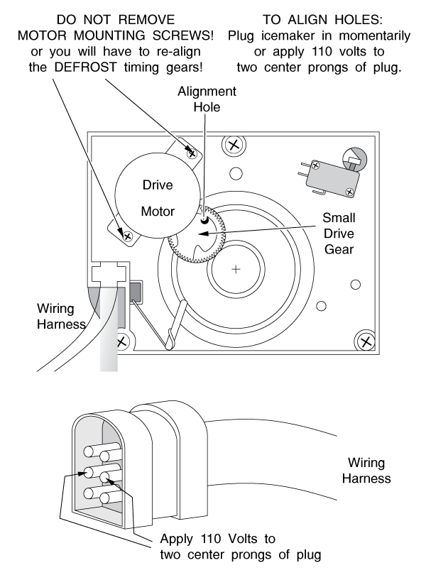
Align the hole in the small drive gear with the alignment hole in the icemaker head and install the gear. Check alignment by inserting a 3/32" rod (a drill bit will do) into the holes to make sure they line up. See Figure 29. If they do not line up perfectly, momentarily plug the icemaker in or apply 110 volt power to the two center leads of the plug This will turn the drive motor slightly. Repeat the process until the holes align.
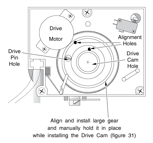
Install the large drive gear and align it on the same alignment hole. A second alignment hole is shown in Figure 30. The large drive gear must line up on both alignment holes and on the large drive cam hole in the center of the icemaker head.
Carefully holding the drive gear in its aligned position, install the drive cam (Figure 31.) Make sure the spring-loaded drive pin is in place in the cam and retained properly; the cam's spring-retainer should be in the pin's groove. Line the drive pin up on its hole on the drive gear. Lift the spring-loaded shut-off arm (ice level sensor) as you install the cam and let it rest in the cam hollow. Be sure that the ice level sensor arm loading spring is in the right place. Install the leaf switch. Sometimes the stuff in this paragraph takes three hands and your belly, but be persistent. You'll get it together.
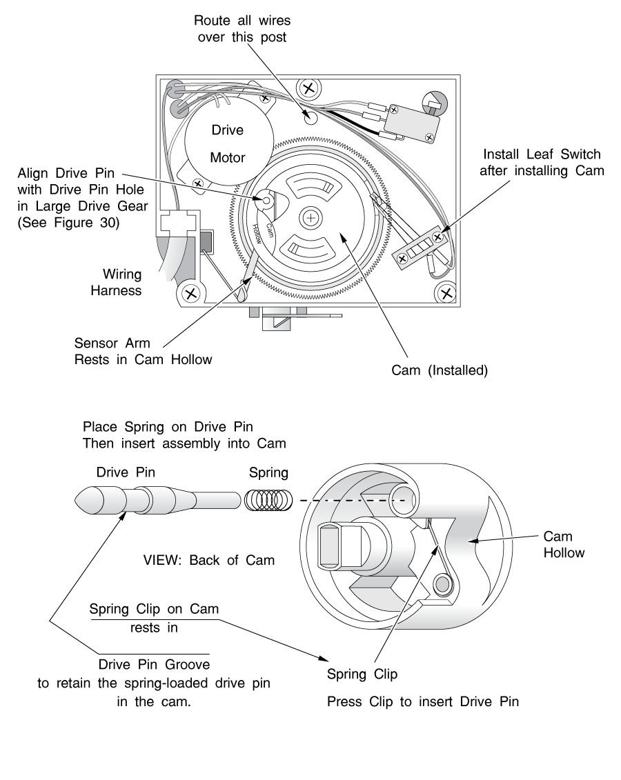
Make sure the wiring for the leaf switch and the defrost switch is routed over the post above the drive gear. Carefully install the metal cover plate, making sure the end of the wire shut-off arm (ice level sensor) is in its pivot hole in the metal cover plate. Install your three screws. The drive pin will pop up through the metal cover plate.
Install the ice tray into the ice maker, and re-assemble your fridge.
The icemaker is now aligned at the beginning of an ejection cycle. When you re-install it, the ice tray will slowly turn 1 full turn. If the icemaker is being used, the tray will then fill with water. Make sure the icemaker is turned on (ice level sensor arm is down) or it won't make ice.
If you have a refrigerator with a hot gas defrost system, the defrost mechanism is somewhat different from those described in previous sections of this book. If you suspect that you might have a hot-gas defroster but you are not sure, ask your appliance parts dealer. Most of these refrigerators were built before 1970, but not all.
The main difference in a hot gas system is that there is no electrical heater or separate terminating thermostat. The defrost cycle is controlled by a defrost timer similar to the one you'll find in electric defrost systems, but the timer controls a solenoid valve instead of a heater. When this valve opens, it diverts the hot Freon gas coming out of the compressor. It then will flow through the evaporator instead of the condenser. The hot Freon gas flowing through the evaporator melts the frost from it. In order to supply the hot Freon gas needed to melt the frost, the compressor keeps running throughout the defrost cycle.
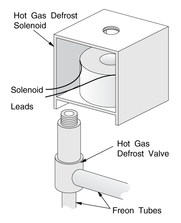
Another interesting feature of most of these refrigerators is that the defrost terminating thermostat was built into the defrost timer. These units have a temperature sensing bulb, similar to that found on the cold control (see section 4-9 and Figures 21 and 33) as a part of the timer. The sensing bulb is led to, and rests against, the evaporator. Its function is to sense the temperature of the evaporator so the defrost mechanism knows when to shut off.
Troubleshooting a defrost problem in this system involves two steps. First, find your defrost timer as described in section 4-5(a). Advance it into the defrost cycle as described in section 4-5(d). The compressor will not stop running. Wait and watch your evaporator for 10-15 minutes.
If the frost starts to melt, then your defrost timer has gone bad. Thoroughly melt the rest of the frost from your evaporator and replace the defrost timer.
If the frost does not start to melt, then your defrost solenoid is probably bad. Fortunately, the defrost solenoid is usually designed so the electrical coil can be replaced without cutting into the sealed system. You will find the coil behind the back bottom panel of the refrigerator. Trace the Freon tubing until you find electrical wires joining the tubing at a certain point. This will be the solenoid valve. (Figure 32). Replace the coil (solenoid) on the valve. Re-assemble your fridge.
The evaporator should be bitterly cold to the touch. In fact, when you touch it, your finger will often stick to it. If the evaporator is either slightly cool or not cold at all, and your compressor is running constantly (not short-cycling; see section 4-9) you have a more serious problem. The same diagnosis applies if just the first coil or two in the evaporator is (are) frosted and the rest are relatively free of ice or perhaps even lukewarm.
What's happening is that the Freon is not getting compressed enough in the compressor. This could be due to two causes: either the amount of Freon in the system is low, or the compressor is worn out. It's time to call a technician out to your home, if you feel your fridge is worth saving. It may only require recharging the Freon system, which, depending on the refrigerant used, may cost you a little, or a LOT. I have only seen one exception to this diagnosis, and this is described in section 7-2.
Don't let the age of the refrigerator affect your diagnosis. Not too long ago, one of the largest appliance companies put out a series of refrigerators with compressors that were either poorly designed or poorly constructed; I never did find out which. These were their giant, 20 to 25 cubic-foot flagship models, with techno-marvelous gadgets like digital self-diagnosis and ice and water in the door, and they were built with compressors that wore out within 2 years.
Fortunately, the biggest and best companies warrant their refrigerators for five years or more, so these refrigerators were still covered under warranty. In my opinion, there is a real advantage to buying brand-name appliances.
If your refrigerator is cold but not as cold as usual, and you cannot trace it to any of the other problems in this chapter, your cold control may be defective. To test its cut-in and cut-out temperatures, you can try putting the capillary bulb in ice water and measuring the temperature with a thermometer, but it's a wet, messy, job and it's difficult to control the temperatures. It's easier to just try replacing it and see if the fridge starts acting properly.
If you hear your compressor "short-cycling" (starting and stopping at short intervals) try jumping across the two leads of the cold control with an alligator jumper. If there is a green third lead, ignore it for this test; it is the ground wire. If the fridge starts running constantly, the cold control is bad. Replace it.
To test or change the cold control, first find it as described in section 4-1. Pull the knob off it and remove any plastic cover plate or housing from it. (Figure 33)
You will see two wires leading to it. There will also be a thick, stiff CAPILLARY TUBE attached. The capillary tube is the liquid-filled temperature-sensing element of the cold control, and operates in the same manner as a thermometer
bulb; in fact, the end of the capillary tube may have a bulb. The tube and bulb may be coiled right next to the cold control, or they may be led away to another part of the compartment.
If you are just testing (electrically) the cold control, you can jumper directly from one wire lead to the other. By doing this, you are closing the switch manually, and assuming the machine is not in the defrost mode, the compressor should start.
If you are replacing the cold control, it will be necessary to trace where the capillary tube goes, and remove the whole tube with the cold control. The new tube is replaced directly. Be careful not to kink the new tube (bend it too sharply) when installing it.
Please share our .